How we deal with the different parts - disciplines and what impact modular construction has, we briefly explain below. For detailed information and specialist data, please find links to the presentations at the bottom of this page.

Systems Engineering
Presentation
Primair en Civiel
Presentation
Lijnen, EMC & Aarding
Presentation
Secundair en telecom
Presentation
Systems Engineering has been applied to each module. Systems Engineering ensures a traceable and retraceable process. So we know which requirements the design meets. This ensures the quality of the delivered high-voltage substation
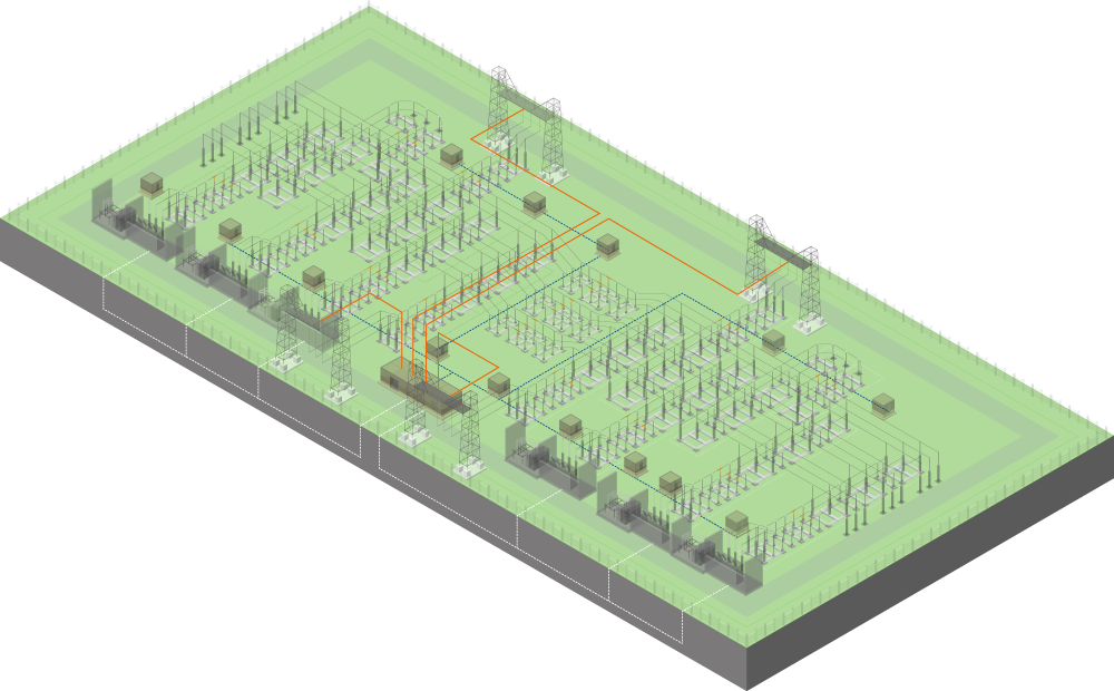
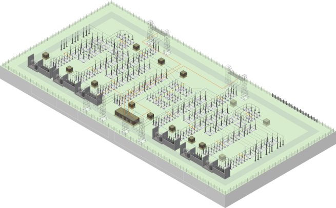
Primary, civil and structural engineering
The site layout, i.e. within the fences of the high-voltage substation, was also included in the modular design. With the exception of a few elements. The fencing, sewerage and paving, for instance, were not designed modularly. We have only defined the preferred materials to be used. Outside the grounds of the high-voltage substation, we take spatial integration into account as much as possible, and we also have to deal with requirements and wishes of the municipality, province or national government - the competent authority. To fit in the substation, we look at nature-inclusive construction, ensure biodiversity and participation, as stipulated in the Environment Act, is also an important framework.
Primary elements
Among others, the primary elements line bay, transformer bay, cross-coupling bay, longitudinal coupling bay and 50kV coil bay are designed modularly. These are designed three-dimensionally and include top and side views, calculations, arrangement drawings and steel drawings.
Civil elements
The civil elements of a substation are underground. In a high-voltage substation, the buildings are built on a foundation. The modular designs for the foundation consist of two variants:
concrete slab design,
pile-founded design.
Which design is used depends on the composition of the soil of the site on which the high-voltage substation is built.
Civil engineering aspects
The central service building (cdg), bay houses, 50kV coil building and the transformer building are modular in design. This means that the buildings have standard dimensions and contain fixed elements. This ensures uniform construction at all newly built high-voltage substations. When developing this modular design, we assumed 'the maximum scenario'. This means that certain designs are wider than necessary in some configurations. This is a deliberate choice to enable faster and more efficient construction.


Earthing
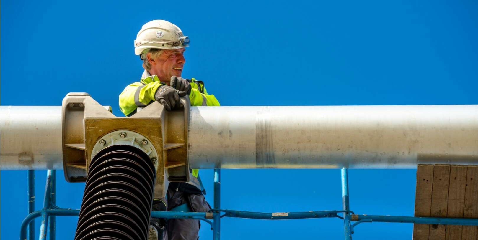
Lines - Line portal
Telecom
Secundary
The secondary part of the high-voltage substation comprises the cables between the components, the bay houses and the central service building. The secondary package is developed for each bay module and includes the function, ground, and power circuit diagrams. Telecom provides communication between the central service building and the national control centre where the high-voltage grid is monitored 24/7.
Safety first! Our and your safety is always our priority. That is why the connection diagrams, which contain an important piece of security, are also designed as standard. The wiring, with which the installation operates, is laid down in a standard. This is protected.
Secondary and Telecom
Systems Engineering
The gantry forms the link between the station and the overhead line connection. We have developed two modules for the line portal that are suitable for a single-circuit, or 'single-circuit'. The standard line portal is suitable for large line angles (45°). The 'light' line portal is suitable for smaller line angles (30°). The light variant can also be used as a modular design to create a so-called 'multi-circuit' line portal.
Electromagnetic Compability (EMC), ensures that the various elements do not affect each other negatively. For this purpose, a toolkit has been developed that allows you to investigate what fits best in which specific situation. In buildings such as the central service building and bay houses, this is now designed within a standard. Depending on the configuration of the station, choices can be made in this.
Earthing all components, possibly eliminating or minimising the difference in voltages, is a requirement. To ensure that no dangerous situations can arise, we have developed a grounding design for each bay according to the modular building blocks.
Electro-magnetic Compatibility & Earthing
For detailed information and specialist data, find the presentations below. You can also put your question to the engineers and experts involved in the modules. You can sent your mail to modulairbouwenlpn@tennet.eu.


Systems Engineering
Presentation

Primair en Civiel
Presentation
Lijnen, EMC & Aarding
Presentation
Secundair en telecom
Presentation
For detailed information and specialist data, find the presentations below. You can also put your question to the engineers and experts involved in the modules. You can sent your mail to modulairbouwenlpn@tennet.eu.
Systems Engineering has been applied to each module. Systems Engineering ensures a traceable and retraceable process. So we know which requirements the design meets. This ensures the quality of the delivered high-voltage substation
Systems Engineering
The gantry forms the link between the station and the overhead line connection. We have developed two modules for the line portal that are suitable for a single-circuit, or 'single-circuit'. The standard line portal is suitable for large line angles (45°). The 'light' line portal is suitable for smaller line angles (30°). The light variant can also be used as a modular design to create a so-called 'multi-circuit' line portal.
Electromagnetic Compability (EMC), ensures that the various elements do not affect each other negatively. For this purpose, a toolkit has been developed that allows you to investigate what fits best in which specific situation. In buildings such as the central service building and bay houses, this is now designed within a standard. Depending on the configuration of the station, choices can be made in this.
Earthing all components, possibly eliminating or minimising the difference in voltages, is a requirement. To ensure that no dangerous situations can arise, we have developed a grounding design for each bay according to the modular building blocks.
Earthing
Lines - Line portal
Electro-magnetic Compatibility & Earthing

Telecom
Secundary
The secondary part of the high-voltage substation comprises the cables between the components, the bay houses and the central service building. The secondary package is developed for each bay module and includes the function, ground, and power circuit diagrams. Telecom provides communication between the central service building and the national control centre where the high-voltage grid is monitored 24/7.
Safety first! Our and your safety is always our priority. That is why the connection diagrams, which contain an important piece of security, are also designed as standard. The wiring, with which the installation operates, is laid down in a standard. This is protected.
Secondary and Telecom
The site layout, i.e. within the fences of the high-voltage substation, was also included in the modular design. With the exception of a few elements. The fencing, sewerage and paving, for instance, were not designed modularly. We have only defined the preferred materials to be used. Outside the grounds of the high-voltage substation, we take spatial integration into account as much as possible, and we also have to deal with requirements and wishes of the municipality, province or national government - the competent authority. To fit in the substation, we look at nature-inclusive construction, ensure biodiversity and participation, as stipulated in the Environment Act, is also an important framework.
Civil elements
The civil elements of a substation are underground. In a high-voltage substation, the buildings are built on a foundation. The modular designs for the foundation consist of two variants:
concrete slab design,
pile-founded design.
Which design is used depends on the composition of the soil of the site on which the high-voltage substation is built.
Primary elements
Among others, the primary elements line bay, transformer bay, cross-coupling bay, longitudinal coupling bay and 50kV coil bay are designed modularly. These are designed three-dimensionally and include top and side views, calculations, arrangement drawings and steel drawings.
Civil engineering aspects
The central service building (cdg), bay houses, 50kV coil building and the transformer building are modular in design. This means that the buildings have standard dimensions and contain fixed elements. This ensures uniform construction at all newly built high-voltage substations. When developing this modular design, we assumed 'the maximum scenario'. This means that certain designs are wider than necessary in some configurations. This is a deliberate choice to enable faster and more efficient construction.
Primary, civil and structural engineering


How we deal with the different parts - disciplines and what impact modular construction has, we briefly explain below. For detailed information and specialist data, please find links to the presentations at the bottom of this page.